ICT Guide - New Regulation for Common Telecommunication Infrastructure
The aim of this guide is to provide up-to-date information on the regulations that apply to telecommunications installations, known as ICT2. As technologies are advancing by leaps and bounds, so do the regulations.
The update of the regulations governing common telecommunications infrastructures for access to telecommunications services inside buildings adds fibre optic and twisted pair cables, in addition to coaxial cable and the traditional copper pair, among the access networks to buildings. It also updates radio and TV technical regulations to adapt them to the DTT scenario.
1. Parts of an ICT Installation - Dimensions
Any telecommunication installation can be executed superficially, recessed or by troughs and trays. The ICT standard regulates which conduits must be installed at each point of the installation, as well as the size of the registers, pipes and trays. The parts of an ICT installation are as follows:
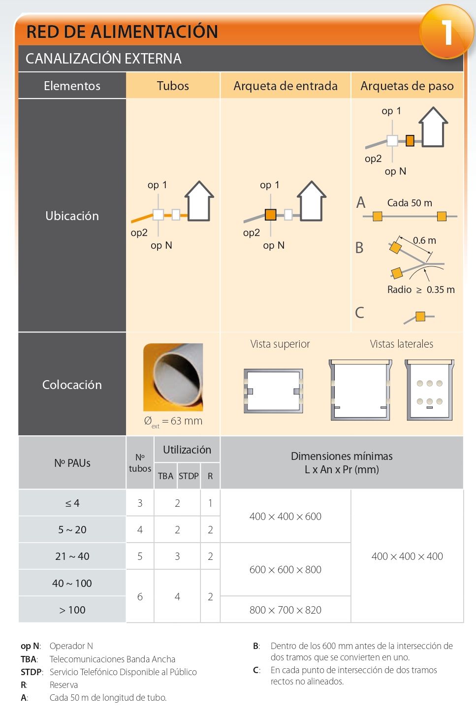
1. Power supply network - external trunking.
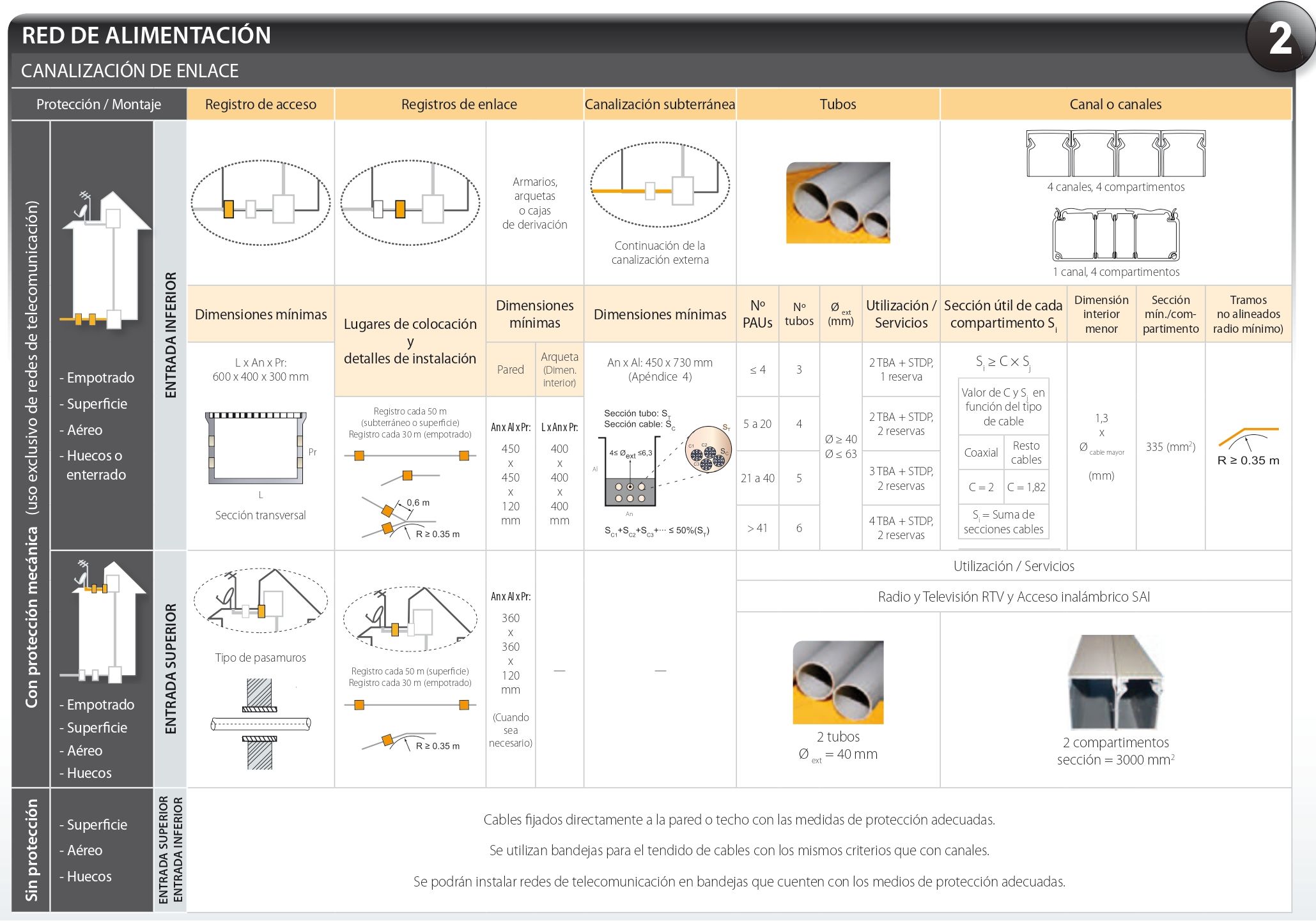
2. Power Supply Network - Link Channelling
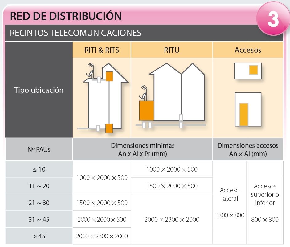
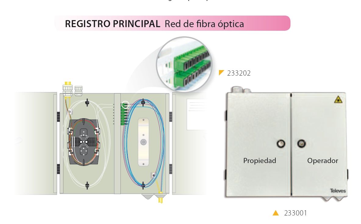
3. Distribution Network - Telecommunications Enclosures
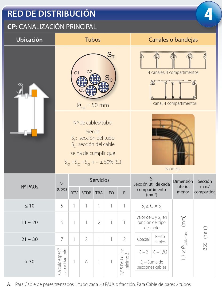
4. Distribution Network - Main Trunking
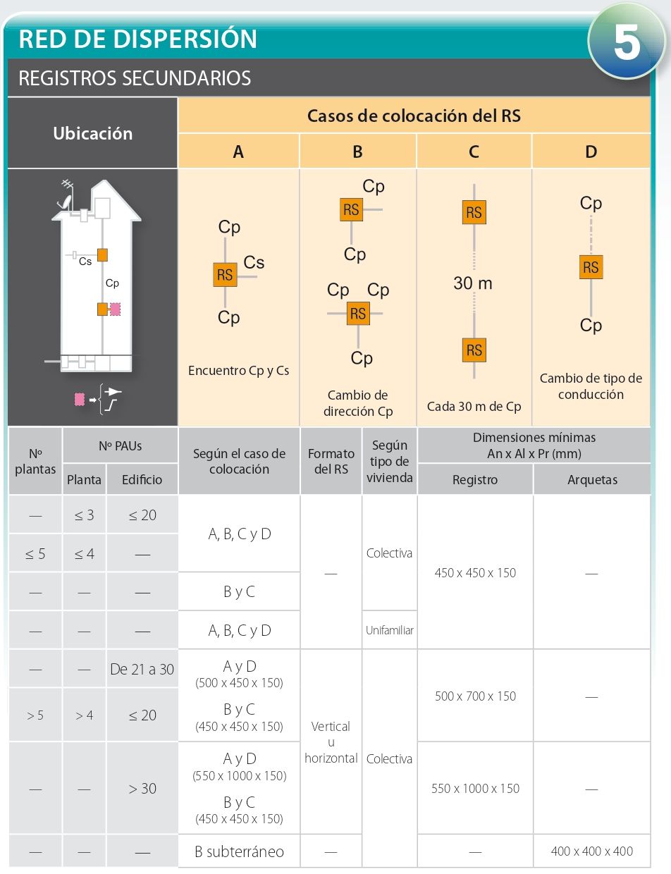
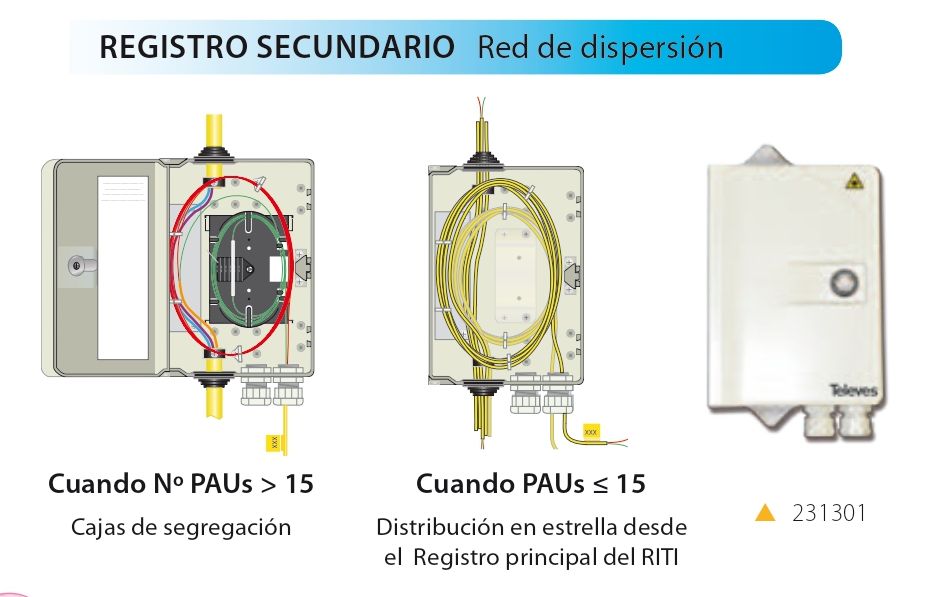
5. Dispersion Network - Secondary Registers
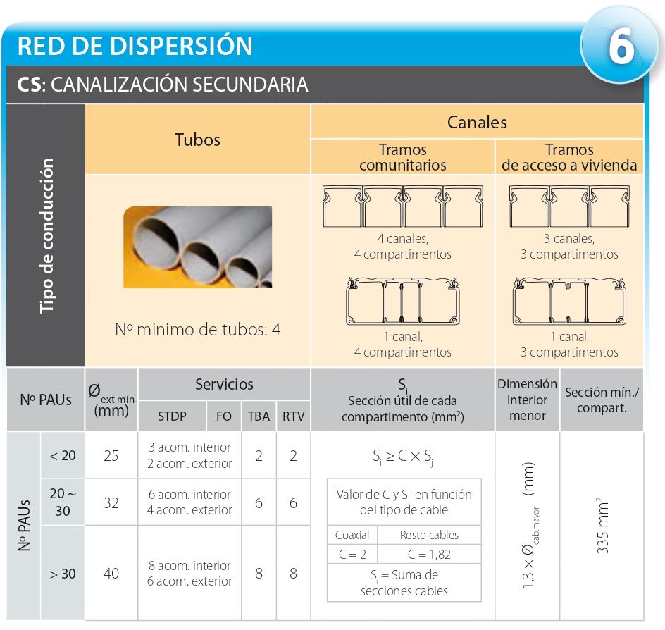
6. Dispersion Network - Secondary Canalization
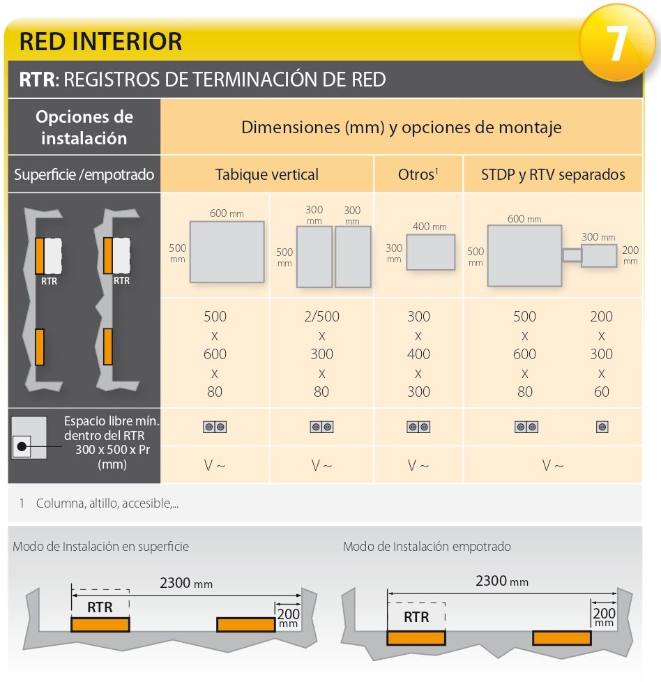
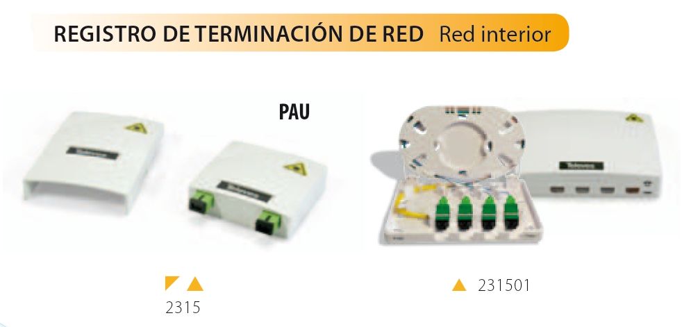
7. Interior Network - RTR Network Termination Records
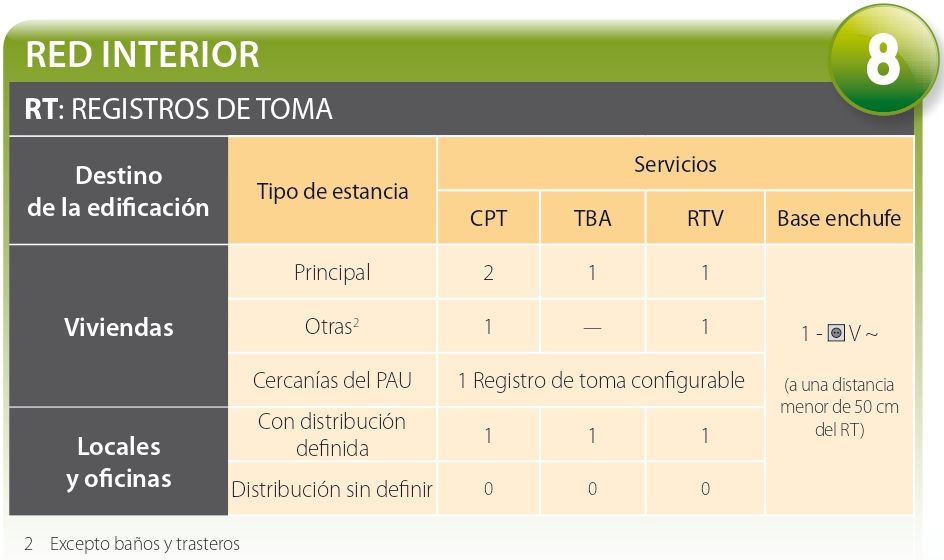
8. Interior Network - Tap Registers
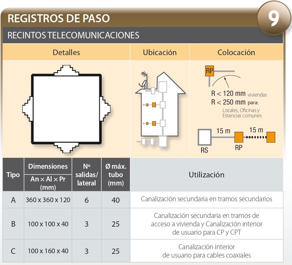
9. Pass-Through Registers - Telecommunications Enclosures
2. ICT Network Requirements
The necessary cables will be installed inside the manholes, pipes and channels to provide service to the different telecommunication networks installed in an ICT. Currently, the networks that are installed are as follows:
1. RTV - SAT
2. UTP Cable - Coaxial Cable
3. Optical Fiber
3. Protocol ICT Regulations
Once we are clear about what an ICT is and what it is for, a series of documents must be prepared in order to comply with the regulations. These steps are as follows:
1. Original Project
2. Verification of the technical project
3. Telematic processing
4. Information Exchange
5. Result of the Exchange
6. Execution of the technical project
7. Installation / Execution
8. Testing protocol and End of Work Certificat
9. User's Manual
4. Basic Definitions and ICT Entities
- ICT: Common Telecommunications Infrastructure
- RITI: Lower Telecommunications Facilities Precinct 546601
- RTR: Network Terminal Register
- RS: Secondary Register
- PAU: Access Point
- RJ45: UTP Cable Connector
- SETSI: Secretary of State for Telecommunications and the Information Society
- MITyC: Ministry of Industry, Tourism and Trade
- ENAC: National Accreditation Entity
- JPIT: Provincial Head Office of Telecommunication Inspection
1. Parts of an ICT System - Dimensions
Any telecommunication installation can be executed superficially, recessed or by troughs and trays. The ICT standard regulates which conduits must be installed at each point of the installation, as well as the size of the registers, pipes and trays. The parts of an ICT installation are as follows:
External Channeling
Link Channeling
Secondary registers
- Minimum dimensions: 450x450x150mm
PAUs < 21 and PAUs per floor <= 3
PAUs per floor <= 4 num. floors in building <= 5
Always in single-family dwellings - Minimum dimensions: 500x700x150mm
21 < No. PAUs <= 30
No. PAUs <= 20 when No. of floors in building >5 - Minimum dimensions: 550x1000x150mm
Nº PAUs > 30
Secondary Canalization
Tap Registers
Telecommunications Enclosures
2. ICT Network Requirements
Inside the manholes, pipes and channels, the necessary cables will be installed to provide service to the different telecommunications networks installed in an ICT.
REDES DE DIFUSIÓN SONORA, TELEVISIÓN Y SATÉLITE
- Proteger los elementos de la infraestructura para evitar efectos de los servicios LTE/4G. Liberación de las frecuencias entre 790 y 862 MHz
- Uso LIMITADO de cualquier tipo de central amplificadora o amplificador de banda ancha en cabecera en edificaciones con menos de 30 tomas
- Toma para señales COFDM-TV: 47 - 70dBμV.
- Se implementa la medida MER en las tomas: ≥21dB (aconsejable mínimo 22dB). MER mínimo en antena para distribuir canal digital: 23dB
- Nivel máximo de salida para cabecera entre canales iguales: 3dBμV
- Niveles máximos de salida para las cabeceras con los valores:
* Señal Analógica: 47-862 MHz: 120 dBμV
* Señal Digital: 47-862 MHz: 113dBμV
* Señal Analógica/Digital: 950-2150 MHz: 110dBμV
MATERIAL RECOMENDADO
UTP
Se emplean cables UTP: entre PAU y el interior de la vivienda y entre RITI y el RTR
Requisitos Cable UTP:
LSFH: Cable Libre de halógenos indispensable
CAT6: Categoría 6 mínimo
CPR: Dca mínimo (Contruction Products Regulation)
Distribución:
Distancia >100 m: Distribución en RS. Usaremos regletas de 5 ó 10 pares
Distancia ≤100 m: Distribución estrella en RITI. RS como elemento de paso. Terminación en RTR con conexión RJ45 al Multiplexor Pasivo, con tantas salidas como estancias. Mínimo dos tomas dobles con RJ45 hembra
MATERIAL RECOMENDADO
A pesar de no estar recogido aún en la normativa ICT2, la mayoría de proyectos a día de hoy sustituyen el Multiplexor Pasivo por un Switch, ya que resulta mucho más práctico.
COAXIAL
Normalmente no se llega a ejecutar en una obra ya que en la consulta de operadores se suele considerar como una instalación anticuada.
Topologías de instalación:
Estrella (PAU ≤20): Cable coaxial recorre desde el registro principal, a través del RS, hacia el RTR terminando en un repartidor de 2 salidas.
Arbol-rama (PAU >20): Uno o varios derivadores en cada RS, dando desde estos cobertura a los RTR existentes y terminando en un repartidor de 2 salidas.
En caso de incorporarse, recomendamos:
- Hoses:
No. of PAU <= 15:
Independent hoses of 2 optical fibers ( red and green) from RITI Main Optical Register to RTR.
Provision* will be left inside the segregation box (231301), present the RS, and with a length equal to the distance from the farthest RTR on each floor.
No. of PAU >= 15:
1 or more multifiber FO hoses run through the RSs.
From these a 2 fiber optic hose (red and green) is sent to the Optical PAUs at the RTR.
- Perform merges or splices at each segregation box of all RSs.
- Buildings with multiple verticals will be treated as a separate distribution network
3. ICT Licenses and Permits Protocol
The steps to obtain ICT2 permits and licenses are as follows:
- Original Project
- Include at least: plans, specifications and budget. - Verification of the technical project
- Approval of the ICT project and verification of the requirements of the New Regulation by ENAC*. - Telematic Processing - 3 copies
- Electronic submission of a verified copy of the technical project to MITyC*.
- Submit a copy to the City Hall, to obtain a building permit.
- Keep a copy for the owner of the building property. - Exchange of information between designer and operators
- Electronic management through SETSI
- Request, in the area foreseen for building, to operators with network deployment. Include location plan of the entrance chamber, data of the developer and the designer.
If necessary, include an alternative location plan for the ICT inlet manhole.
- SETSI will forward all operator responses to you within 30 calendar days. - Result of the Exchange
- Depending on the outcome of the responses from the operators, the modifications will be incorporated in the staking report and in the annex of the technical project. - Execution of the technical project
- The promoter and the author of the staking out report must sign the report to validate the original project and its update. It can be included as a modification or in the annex, depending on the importance of the changes.
- Submit a copy of the report electronically to the MITyC registry within 15 calendar days. - Installation / Execution
- After the execution, the installation company must deliver to the owner of the property an installation bulletin guaranteeing that it complies with the technical project. - Test protocol and End of Work Certificate
- Without site management: The installation company will sign the test protocol, and will attach the pertinent changes in the annex.
- With site management: ICTs more than 20 dwellings, with active elements or in non-residential buildings.
The management will review the test protocol and deliver it to the owner of the property together with the completion certificate.
- The owner of the property will electronically submit to the MITyC:
Installation Bulletin, Test Protocol and Certificate of Completion.
The JPIT* will return a stamped copy to be included in the Building Book.
- Granting of licenses and permits of first occupation, in new buildings.
To present to the competent Administration:
Certificate of Completion of Work, Telecommunications Installation Bulletin, Test Protocol and Certificate of Completion of Work stamped by the JPIT*. - User Manual
The ICT work management, or the installation company, will deliver a copy of the user's manual to be given to each of the owners.
We hope that this guide will be a useful tool for those professionals and companies working in the telecommunications field, and that it will enable them to comply with the latest regulatory provisions to ensure the safe and efficient use of telecommunications installations.
1. PARTS OF THE ICT INSTALLATION
2. REQUIREMENTS ACCORDING TO TYPE OF TELECOMMUNICATIONS NETWORK
3. PROTOCOL